8 THE BELLFRAME
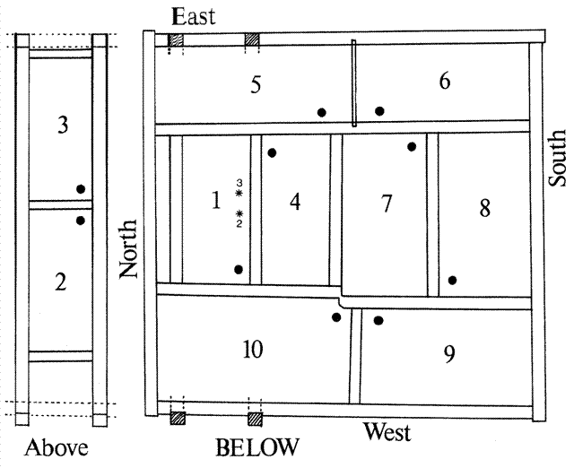
8.1 The bells hang in a two-tier frame (Plate 1, 2 etc). They were originally hung on one level (Figure 3) in a frame built or reconstructed by Samuel and Robert Turner of Whitechapel in 1764. When two more bells were added in 1885-6 Mears & Stainbank provided additional framework (Figure 4) to accommodate bells 2 and 3 of the augmented ring. The upper frame is positioned on the north side of the tower.
8.2.1 Position and foundations: The lower frame is positioned near the bottom of the belfry window openings, with the heads a little above the door into the bell chamber and above the sills of the windows. The bell chamber floor is entirely independent and some two or three feet below the bottom of the frame (Figure 1). The frame is supported on four large east-west beams and with four secondary bearers (doubling as sills for the main north-south trusses). The sills are framed on two levels with halving joints (Figure 2).
8.2.2 The upper frame of 1885-6 is carried on upright posts fixed between the heads of the lower frame and the underside of the tie-beams along the east and west walls (Figure 5 and Plate 1, 11, 12). In 1961, additional steel brackets were added below the middle of the sills of the top frame to provide extra support (Plate 1 and Figure 5).
8.3 Plan: The lower frame is of traditional eight-bell plan (Bellframes layout 8.3) with pairs of bells swinging mouth-to mouth on the east (now bells 5 and 6) and on the west (bells 9 and 10), with four bells (bells 1, 4, 7 and 8) swinging east-west in parallel pits in the middle (Figure 3). In the upper tier, the two bells (bells 2 and 3) swing mouth-to-mouth and east-west (Figure 4). When the bells were augmented to ten, the treble of the old octave (now no.3) was moved into the upper tier with the second bell of the ten and the new treble was hung in the vacated pit in the lower frame.
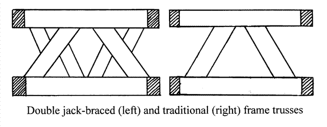
8.4 Truss types and return sections: The lower frame is essentially of double jack-braced construction (Bellframes type 6.D) with minor variations (Plate 3, 4). The return sections are of similar type (Figure 7). Simple diagonal braces (using curved timbers) are used as spacers between the pits accommodating two bells mouth-to-mouth on the east and west sides of the tower (Plate 6-8). The top frame (Figure 4 and Plate 11, 12) is a standard wooden lowside construction (Bellframes type 6.A) of 1885-6 with jack-braced return sections. Simplified sketches of these truss types are illustrated below:
8.5 Unusual features: The most significant feature in this frame is the stepped head between the pits of the ninth and tenor bells (Plate 9, 10). This was done is order to make the pit of the tenor bell wider than that of the ninth, using the device of a step in the heads to give the extra width (Figure 3). In consequence two of the parallel pits (those now housing bells 1 and 4) are shorter in length than the other two (housing bells 7 and 8). While such an arrangement is not uncommon, it is very unusual for this to be done – as it is here – using a single span of timber. Another feature to note is that the outer truss of the treble pit has been built within the space available (shown on the left in Figure 2, 3), leaving a narrow space between the outer truss and the head running along the north wall.
8.6 Strengthening: The lower frame has been strengthened by the insertion or iron tie-rods and metal plates at various times. These include:
- Large flat metal plates fixed to the heads in the main angles of the lower frame (marked on Figure 3). Those in the corners are L-shaped and those at the intersections are T-shaped, all with diagonal side-members for added strength (Plate 3, 4). There is one old T-plate in the middle of the western truss (Plate 7, 8)
- Vertical iron tie-rods have been fitted through the frame in several places (Figure and ph. passim). These tie-rods appear to be of several different dates. The earliest of these are the stout iron tie-rods - mostly fitted at an angle diagonally through the frame and with the bolt on the underside - as shown in the truss drawings (Figure 5, 6, 7 and marked with a plain (box) symbol on the plan in Figure 3).
- Heavy iron angle-plates have been fitted inside the corners at the intersections of the heads in many places (Plate 3, 4 and figures passim etc), again at several different dates. The area round the stepped head has been extensively angle-plated (Plate 9, 10)
8.7 Reused timbers: While the lower frame evidently dates 1764 as a structure, some older timber has been reused. Several of the main braces are substantially larger than would have been used in 1764 and may well have been reused from an older frame. There are re-used curved braces in several places, notably in the north end of the tenor pit, a lower jack brace in the west side of the tenor pit and in the spacer pieces in the middle of the east and west sections of the frame. The main bearers - as already noted - are much older than the present frame.
8.8 Pegs, marking, cut-outs etc: The lower frame is of mortised construction throughout, the joints being secured with pegs (as indicated in Figure 5, 6, 7). Generally there are three or four pegs where the braces join the sills and the heads, and two pegs at each end of the jack braces. Some of the joints (e.g. in the south truss) are numbered with Roman numerals (some on southern truss p-q are shown in Figure 7). There are cut-outs or clearance grooves in the heads in some pits in the lower frame.
© Copyright 2006, Chris Pickford
 ABINGDON BELLS: Bellframe
